Testing the LEDs
The LEDs on the sidelight PCB are Surface Mount Devices. If you look closely, you will see that they have a diagonal cutaway at the top left hand corner. This is clearly seen on the photos of the LEDs below. This identifies the cathode and corresponds to the flat side and short leg on a standard LED (in most cases).
Note
On some type of SMD LEDs, the diagonal cutaway represents the anode. Always check with the data sheet and preferably test the LED to confirm the anode / cathode side before before fitting it. Remember, LEDs can be damaged by ESD and heat. Take care when soldering.
The photos of LD53 (blue) and LD16 (red) show what the SMD LED looks like close up. There is no physical difference or identifying marks between the colours. LD16 shows a damaged LED. This was caused by short circuiting it direct to GND, the LED exploding internally as it melted and it went open circuit. When you have LEDs not working, look for anything out of the ordinary that might give a clue as to a LED possibly being faulty. However, if an LED looks damaged, do not assume that that LED is defective, test it first (it will probably need replacing anyway). Likewise, if an LED looks exactly as it should do, it doesn’t necessarily mean that it’s working correctly. Test all LEDS in a group as detailed below when that group isn’t working.

Fig. TL1: Good and bad LEDs
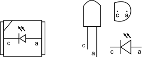
Fig. TL2: Identifying the pin-
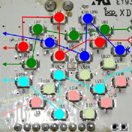
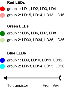
Fig. TL3: The LED groups and their connections
The LEDs can be damaged by static electricity, so take normal ESD precautions before touching them. Also, allow a few minutes for the capacitors on the board to lose their charge.
There are various methods to test the LEDs. The red circuit group 1 will be used as an example.
Using a diode tester
The first test is via a diode tester and can be done with the PCB or sidelight unplugged. This is the safest way of doing a test because there is less risk of a potential short and damage to other components than when the board is live. Many digital multimeters have a diode tester built in and, when selected, they pass a small current through the diode. When a LED is being tested, this current causes the LED to light up if it is working. Depending on the multimeter, it may also display the forward voltage of the LED. (My Precision Gold multimeter does, the cheap Maplin one just shows 1 as soon as diode test is selected). The forward voltage of the SMD red LED is around 1v698. The green and blue LEDs are higher. If your multimeter only reads up to 1.999, then the voltage will not be displayed and you will get an overload indication (normally O.L). The LED will still light up on test, though, as long as it’s not faulty.
Connect the black COMmon meter probe to the LED cathode and the red probe to the anode. This should not damage the LED, but to be certain, it might be better to use a current limiting resistor in series with one of the meter probes.
Only the LED being tested will light (if it is working). If the LED doesn’t light, it’s possible that the LED is faulty or you might have the tester probes the wrong way round. Reverse the probes and try again.
If all the LEDs work as you test them, then it’s possible that the associated transistor (T4) is faulty. Check the voltage at TE11.
If at least one of the LEDs work, then the transistor is probably OK and the LEDs that didn’t light are faulty.
If none of the LEDs work, then it’s possible that all four are dead. Repeat the test. If you still get the same result, try the Resistor test. and or the Substitute LED test.
The diode test will only light the LED that is between the probes. If there is more
than one LED between the probes, no LEDs will light because there is insufficient
current from the meter -
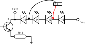
Fig. TL4a: Using a diode tester Fig. TL4b: Using a diode tester across more than one LED
The following tests are carried out with the sidelight connected and set to max white light (or the max of the colour that’s defective if you want).
WARNING
When working on the LED side of the PCB, be careful when testing around LD1, LD5, LD6 LD9, LD10 and LD16 because the pins from the electrolytic capacitors on the other side of the board are very close. Likewise, be careful when testing around LD2, LD11, LD35 and LD54, because of the closeness of U1.
A short circuit between one of these connections and the LED could damage the LED.
If you are resting the PCB on a table or bench while working on the LED side, beware of bare wires or anything on the table that may short against the components on the component side of the PCB.
Likewise, be careful if working on the component side and resting the LED side on the table. On the LED side, beware of shorting the J5, cap or pot connections on the PCB to the LED connections.
Substitute LED test
In this test, another LED is used to “piggy-
Take an ordinary LED, preferably the same colour. Start with the first LED in the
group. Place the cathode over the side of the LED with the diagonal cut-
If there is only one LED in the group that is faulty, the substitute LED will light
up when it is placed over the contacts of the dud LED. As it’s now completing the
circuit, the other LEDs in the group will light up too. If you have tried all the
LEDs in the group and none have lit, it’s possible that you have the substitute LED
the wrong way round and are not connecting the cathode of the LED to the diagonal
cut-
If no LEDs work, it’s possible that all four could be faulty or the associated transistor is faulty. Try and prove the LEDs are OK by doing the Diode tester test or Resistor test.
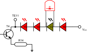
Fig. TL5a: Using a substitute LED
LD13 is faulty
The LED bridges LD13 and lights up
Because the VCC path is now complete, the other LEDs now light
The photos below show a substitute LED being placed over faulty LD16. When the LED is touching the contacts of LD16, it completes the circuit. The LED lights up, and so do LD13, 14 and 15.
The leads of the LED should be bent slightly in order for them to fit over the PCB LED. The LED leads can then be placed over the contacts and gently pressed (like tweezers).
See the warning above


Fig. TL5b: Preparing to place the substitute LED over LD16. Fig. TL5c: Holding the substitute LED in place
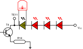
Fig. TL5d: Using a substitute LED
LD15 is faulty
The LED bridges LD15 and lights up
Because the VCC path is now complete, the other LEDs now light
Resistor test
This test uses a resistor to provide an alternative return path to GND instead of the transistor.
Connect one end of a 270K resistor to GND. The simplest way to do this is to use
a lead with a crocodile clip at each end. Connect one end to the resistor, and the
other end to the shell of the USB cable plug at the PC. Touch the other end of the
resistor to the cathode of the LED, beginning with the LED nearest the test point
(LD15). Any LEDs between the resistor and VCC will light up if they are working with
no faulty LEDs in between -
If all LEDs light when the resistor is placed at the cathode of LD15 (or TE11). Then it’s possible that there is a fault with R8, T4 or R14. If no LEDs light. Confirm that the resistor is still connected to GND and try the test once more. If you still have no LEDs lighting during the test, it might be that all four LEDs are faulty. Try and prove whether any of the LEDs are working or not by doing the Diode tester test.
Note -

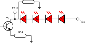
Fig. TL6a:
Resistor at LD15 cathode / TE 11
No LEDs are faulty
All LEDs are lit

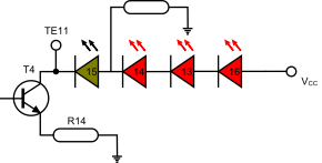
Fig. TL6b:
Resistor at LD14 cathode
LD15 is faulty
LD14 -
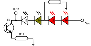

Fig. TL6c:
Resistor at LD13 cathode
LD14 is faulty
LD13 and LD16 are lit
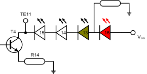

Fig. TL6d:
Resistor at LD16 cathode
LD13 is faulty
LD16 is lit
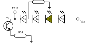
Fig. TL6e:
The resistor is at the cathode of LD14. Although there is nothing
wrong with LD14, it will not light because there is no VCC passing through faulty LED13.
