Repairs
Warning!
When checking things out on an accessory, Be careful!. The components on the PCB
are close together. The slip of a test prod or a screwdriver could create a short
circuit and potentially damage the sidelight or wallwasher. Unless you need the accessory
plugged in to test, unplug it from the wallwasher. Remember that the PCBs are double-
ESD
Many components can be damaged by static electricity (Electro Static Discharge),
this includes the LEDs. Remember when you used to rub a balloon up and down your
jumper then stuck it on the wall? -
Whilst the PCB has ESD protection, you still need to be careful and take precautions. If you are replacing a component, such as an LED, this will be unprotected until it is soldered into place. Many surfaces can hold static electricity, and this can be transferred to a component if you’re not careful.
Take normal anti-
Use your common sense. I must admit that I’ve rarely taken all the correct ESD precautions. Careful preparation and handling can eliminate a lot of the risk. Earth yourself and tools before touching the PCB or component and avoid handling them too much. Remember, many soldering irons can be a cause of static, especially if they’re not earthed. One way to get around this is to clip a crocodile clip onto the soldering iron metal body furthest away from the tip (at the coldest point) and connect an earthed cable to the clip. It’s something I’ve done in the past, but I don’t know how effective it is.
Be practical in your choice of where to work on the accessory. An empty table with plenty of light is ideal. Opening an accessory on a nylon carpet with its static properties is not the best choice of work surface (although it’s something I’ve frequently done!). Likewise wearing a cotton shirt or T shirt etc. is better than a synthetic one as cotton is less likely to attract static.
Working on the equipment
Always have a pen and paper to hand to make any notes you want.
Most of what you want to do will probably be associated with the sidelight or the wallwasher. Unless it is necessary for the checks, unplug the sidelight. This will help reduce the likelihood of any damage. Only plug the sidelight in when you need to do checks or alterations with the LEDs on. Likewise with the wallwasher. Remove the PSU plug from the wallwasher whenever possible, especially before unplugging the LED PCB connector cable. Remember, even though the PCB or wallwasher may be disconnected, it’s possible that the capacitors could still retain a charge for a while, especially on the VCC line and could still cause damage if shorted against another component. It’s also possible that it might give you a wrong reading if you’re taking measurements. As an example, on a test on the sidelight PCB, when the sidelight was unplugged, VCC dropped very quickly, but remained at around 1v, slowly dropping to 0v.
If you have to work with the LEDs on, unless you need them at full brightness, turn the brightness down via the individual light setting in the DirectControl panel or something similar. The LEDs are deceptively bright and can cause temporary sight problems or discomfort, even if looking at them for just a short while. If I have to look at the LEDs, I use sunglasses. The colours are still distinguishable.
Resistance readings are taken with the equipment disconnects or switched off at the mains. Voltage readings are taken with the equipment connected and switched on as necessary.
Testing the wallwasher sockets
There are times when you may need to measure the voltage at the wallwasher sockets.
One of the simplest ways is by using thin wire, insulated except for about 3 -
The sidelight connection on the wallwasher has pins surrounded by the shell, which
makes it difficult to get at the individual pins without shorting across them or
the shell. This is easily overcome by connecting a VGA female socket over the pins.
This will then give you access to the connections in the shell. An alternative method,
is to use an all wires connected 15way F-
Remember
The fan, rumbler and sidelight sockets need connections shorted together for the
accessory or the accessory won’t be detected and you won’t get proper readings. It
is important that you short the correct contacts together. Shorting the wrong ones
could damage the wallwasher. Details of the socket pin-
Surface Mounted Devices
SMDs are used a lot in electronics these days, partly because they are generally
cheaper than standard devices, but more importantly, they’re smaller. The amBX system
is no exception. If you’ve never opened the wallwasher or sidelight, then you may
not have seen a SMD -
To quote the official specification size:
0805 Resistors and capacitors used on the PCB: 2.0mm long x 1.24mm wide x 0.45mm thick
Transistors and diodes 3.05mm long x 2.5 mm wide x 1.12mm thick
By comparison, the LEDs are quite large at 3.5mm x 2.7mm x 1.9mm
To put this in perspective, the figure 6 in 6 point Arial text is approx. 2.0mm tall x 1.6mm wide


Soldering
Soldering SMD components is more complicated that ordinary components. For one thing,
there is no easy way to fix a component to the PCB before soldering -
If you’ve never done any SMD work before, practice before actually working on the amBX equipment. Most electronic products have SMDs in them these days and you must have something that’s mot working that you keep meaning to throw away!. Practice desoldering and soldering the components. Remember, that too much heat will probably damage a component, especially LEDs, so you need to solder as quick as possible. Have a look on YouTube for videos on SMD desoldering and soldering.
Tools
Having the right equipment is essential when carrying out SMD work. Whilst you could possibly scrape through using tools that you use for ordinary electronics work, it is much easier when you have the right equipment. The problem is that some of the tools that you should really use are expensive. This doesn’t really matter if you are likely to use them a lot, but if you only want to replace a LED, then buying the tools just for one repair would make that repair very costly, although some tools, like tweezers and a magnifying glass may come in useful when doing other work. Some information on the types of tools that will be a help is given below.
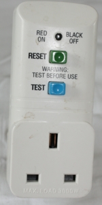
Residual Current Device (RCD)
AN RCD quickly switches off the electricity if there is a fault and can protect against
electrocution. If you are working on mains equipment where the mains is switched
on and there is the risk of contact with any mains connection, use an RCD for your
own protection. Some household supplies may already have RCD protection in the consumer
unit, but it may not cover all circuits. Be safe -
Always use an RCD if you have to open up the subwoofer box.
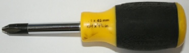
Screwdrivers
Depending on what you want to do, at the very least you will need a screwdriver. Most of the screws in the amBX system can be removed using a Philips no.2 size screwdriver. A no.2 size pozi screwdriver may work, but the Philips one will usually give a better grip. A smaller size may be required for tiny screws.
For places where access is restricted, such when removing the amplifier PCB, a “stubby” (short) screwdriver is ideal.
Soldering iron
Whilst it’s possible you could get away with using an ordinary soldering iron, a “SMD soldering tweezers” soldering iron is much better. This has two solder bits and they are held in the same way as tweezers to apply the heat to melt the solder on both edges of the component. They are also useful when desoldering a component. Get some good quality thin core solder. It’s no good trying to solder a tiny component with a big blob of solder!
Desolder tool and desoldering braid
Although it may be difficult to use a desoldering tool on SMD components, the PCBs
and other equipment still have some through-
Solder
One of the difficulties these days is that newer electronics use lead-
Tweezers
Decent tweezers are essential. Remember, the tweezers will be gripping something that is tiny. You don’t want to use cheap tweezers that don’t meet properly. Likewise, you want to have something with a decent grip on them. Imagine trying to look for something as small as a dried chili seed that has popped out of the tweezers’ grip and fallen on the floor!. A pair of ESD coated tweezers are best. These will give protection against ESD damage when handling the components.
Magnifying glass
You will need a magnifying glass, ideally two types, depending on what you want to
do. For close up work, when examining the PCB or components, then you need a powerful
one. You could use a handheld one, but a hands-
For working on the PCB, you definitely need a hands-
Test the magnifying glass to see if it is suitable before buying it. Take a sample sheet of paper with you with some text printed in normal (not bold) Arial font in font sizes 1, 2, 3, 4, 5, and 6 point. Some of the text on the small components is about the size of 1 point. If you want to be able to read this, you’ll need to make sure the magnifying glass is powerful enough.
Continuity tester
You will need a continuity tester for various checks. There are different ones around, but probably the best way is to buy a cheap digital multimeter. These can be bought for a few pounds and can also be used for testing the voltage at different places. Use the resistance setting. A resistance reading of 000.0 ohms means that the continuity is good. Some multimeters have a continuity setting which will give a continuous tone if the continuity is good. These are better, because you don’t have to keep looking at the meter reading during testing.
Multimeter
A multimeter is essential if you want to check voltages or resistance. It will also work as a continuity tester. Buy a digital meter as this will give you more choice. Generally, you get what you pay for. A cheap one will cover your basic needs and should be reasonably accurate. A more expensive one will have more features. If possible, get one that also has a diode tester. This can be very useful when testing the LEDs.
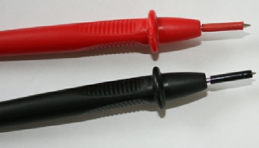
Multimeter cables / probes
Many probes have a long bare tip. The problem with this is that where the components are close together, the probe can short across nearby connections. This is easily solved by putting a piece of sleeving over the probe so that only the tip is left bare (see photo at the end of this page). If you don’t have any sleeving, you could use insulating tape, but experience has shown that that the tape tends to unravel after a while and it also becomes very sticky.
Whilst the probes that come with a meter may do the job, because of the smallness
of the components, some additional probes may be useful. One type are the 4mm SMD
probes from Rapid. These have a fine tip which means they can be positioned more
accurately and there is less chance of them touching an adjacent pin and causing
a short circuit. Another type are the tweezer probes. These are shaped like tweezers,
but with individually isolated tips -
Oscilloscope
Although not essential, if you have an oscilloscope, this can be used for displaying the voltage and also the waveform of the signal. I have a PoScope which plugs into the USB port of the PC and uses the monitor for the display. Whilst it is cheap, and basic, it’s suitable for what I want to use it for. One advantage is that it can display two separate inputs on the screen, allowing me to monitor two separate things at the same time. This is useful if, say, I want to measure the red signal input and the red signal output and compare them.
Sunglasses
These are a must if working with the LEDs on. The LEDs are deceivingly bright and
can cause temporary blindness or a funny sensation in your eyes after looking at
them -
Although not specific to SMD work, I find the following useful when working on anything:
“Pearl catcher” pick-
Precision screwdrivers -
Connectors
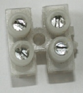
The simplest connector is the “chocolate block” type with screw terminals. You will need one of these if you are removing the amplifier PCB and want to keep the subwoofer speaker connected.
Small container
Have one or more small containers to put the screws etc. in -
Notebook and pencil
Not strictly a tool, but this is a must. I always find that I need to make a note when I’m working on something, even if it’s just a reminder of what screws go where.
Connector links / Flexible jumper wires
These are useful during testing etc.
Clamp
Some form of clamp is advisable to hold the PCB when soldering. It can also be useful
during testing, but it is very important that any metal parts or clips on the clamp
are isolated to prevent short circuits on the PCB. The clamp can either be a bench
fitting type, or a PCB holder of the sort you see with various clips attached. Whatever
you use, make sure that it will hold the PCB rigid. DO NOT OVERTIGHTEN the clamp
on the PCB, especially if you’re using a bench clamp with jaws -
See the Components / Where to buy page for further details about the tools
Top to bottom
0603 resistor (not used)
0805 resistor
1206 resistor
BC818-
Light sensor
Red LED
Right
Comparison with a 1mm scale ruler and 5p coin
connector