Relay PCB
To prevent any risk of electrocution, only open the subwoofer with the mains plug removed from the mains socket. For additional protection when working with any equipment that may be connected to the mains, always connect that equipment to a socket that is protected by a Residual Current Device, or connect that equipment’s plug to a portable RCD that plugs into the mains socket.
Description
The relay PCB acts as the mains ON / OFF switch, turning the current on to the PSU when the wallwasher is on, and turning the current off when the wallwasher is off. 5vDC from the wallwasher energises the relay coil and closes contacts on the live mains supply. This allows the mains supply to go to the PSU.
The relay PCB contains the following components:
Relay
Capacitor
Fuse
3-
2-
2-
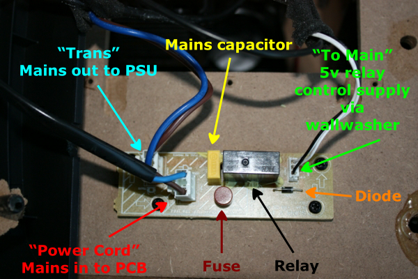
Fig. BR1: Relay PCB -
All the components and the PCB should be treated as live at all times when the subwoofer mains plug is plugged in
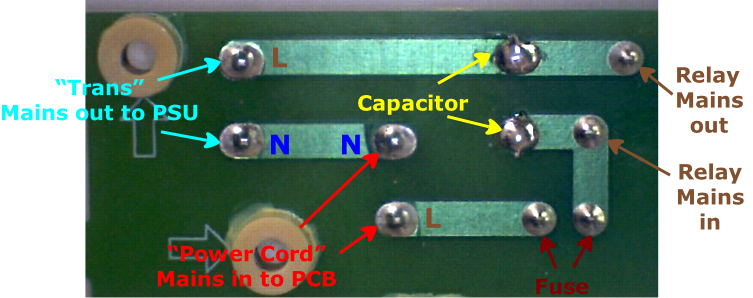
Fig. BR2: Track side of relay PCB -

Fig. BR3: Track side of relay PCB -
When unplugging the mains cables from the PCB, DO NOT FORCE the plugs. There is a little locking tab near the top of the plug. Gently squeeze this and gently pull the plug upwards whilst holding the tab in. The plug should move easily. If it doesn’t, then you’re not doing it right!
Do not rock the plug / socket backwards and forwards. It is easy to damage the solder connections where the socket is soldered to the PCB, and you may break the PCB track altogether. If the Socket is loose / PCB track broken, then you will have to repair the connection.
Remember, this is a high voltage PCB and any damage is a potential fire or safety risk.
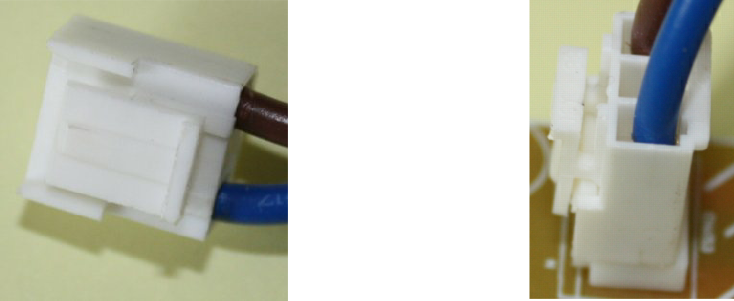
Fig. BR5: Plug with locking tab. Push and hold the tab in at the top when removing the plug
Testing the relay PCB
Make sure the subwoofer mains plug is disconnected
Unplug the 7-
Unplug the two mains plugs from the PCB -
Unplug the 5v relay plug.
Unscrew the PCB from the box
Ensure that the PCB is not resting on anything that could short circuit the tracks.

Fig. BR6: Test locations -
Testing the continuity -
If the relay was not working
On the component side:
Check the resistance between 11 and 12 ( the two outer pins on the 5v socket) -
Switch the wallwasher on and check the voltage between the two outer holes of the relay plug. It should be 5vDC
Connect the 5v relay plug to the PCB
Check the voltage between 11 and 12 (you should be able to access the contacts with the plug in the socket). The voltage should be just over 4v (due to the voltage drop across the diode).
If the voltage reads zero when the relay plug is in and 5v on the plug when it is
out, this could mean that the diode or relay coil has short-
If the relay was working
On the component side:
Check for continuity between 1 and 2 (N in and N out sockets). The reading should be zero. A high reading may mean that there is a poor solder joint on either socket.
Leave the two mains plugs disconnected from the PCB
Ensure that the PCB is not resting on anything that could short circuit the tracks.
Connect the 5v plug back onto the PCB
Connect the 7-
On the component side:
Measure the resistance between 3 and 4 (L in and L out sockets).
If the resistance is zero when the relay is energised and infinite when the relay is off, then this proves that the mains contacts on the relay are working correctly and there is no fault with the relay. It also proves that there is a path from the Live In socket, through the relay contacts, through the fuse to the Live Out socket. The PSU should be getting mains power when the subwoofer is connected to the mains.
If the reading is high, this could be due to a blown fuse, defective mains relay contacts, or problems with the joints or PCB track.
On the track side:
Check for continuity between 7 and 8 (the relay mains in and out joints). A zero reading means that the contacts are closed. A high reading could be caused by faulty contacts or joints.
Check for continuity between 9 and 10 (the capacitor). The reading should be somewhere
around 20 -
Check for continuity between 5 and 6 (the fuse joints). A zero reading means the fuse is OK, a high reading means the fuse is blown and needs to be replaced. A high reading could also be caused by a faulty solder connection at one of the fuse joints, although unlikely.
If the fuse has blown, replace the fuse. If the fuse blows again and the capacitor is OK, the subwoofer PSU may be faulty.
The fuse is a Wickmann fuse (may also be called a “European fuse”). Unlike the cartridge type fuses, it cannot be easily replaced. However, if you have some soldering skills, it is still easy to replace. There are many stockists. See Farnell.
Note. It is important that you use the correct type:
T3.15A 250v type 382 see the Components page for more details
Other faults
Relay permanently on
-
The relay contacts are permanently closed.
No great problem, just switch off / disconnect the subwoofer at the mains when you turn the PC off.
Voltage readings
Voltage readings on the relay PCB with a 5v feed to the relay. Meter is set at DC. The voltage is approximate.
Measured across STBY and +5v on plug when 5v plug is unplugged -
Measured across STBV and +5v on PCB tracks or on plug when 5v plug is plugged in
-
The difference in voltage is due to the voltage drop across the diode.
If the voltage across the plug is 5v when disconnected and 0v when connected, this may be due to the diode being short circuit. Confirm and replace the diode.
Although less likely, a 5v short could also be caused by a short within the relay. This is easily confirmed by removing the diode and testing for 5v again. If it is still 0v, then the relay probably is defective.
A short on the 5v feed doesn’t appear to have much effect on the wallwasher. It may cause devices to show as connected even though they are not and the volume / brightness controls on the speakerlight may not work correctly.
If everything on the relay PCB appears OK, screw the relay PCB back onto the subwoofer box. Connect the two mains plugs and the 5v plug to the PCB.
Make sure the 7-
The power supply may be faulty -