Extending the Cyborg light cables
There are only two cables you may want to extend:
The USB cable (see details near the bottom of the page) and the power supply.
PSU details
The supplied PSU has, according to the PSU, an output of 5vDC at 2A. The PSU has two connections to feed two lights.
The connectors are 1.3mm (centre hole / pin) and have a positive (+ve) centre -
The current drawn by each light varies between 0mA (light off) and approximately 420mA at full brightness white (all three LEDs on full power). The actual current drawn at any particular time depends on the brightness and the colour of the light.
The light uses 1.3 connectors
Note -
Although the PSU states the the output is 5v, the output from my PSU is approximately 4v3 on or off load. I don’t know if this is the same with all the PSUs.
Extending the power supply
Extending the power supply is easy. Position the lights
where you want them, then use the nearest mains socket or use a mains extension lead.
If you just have two lights and have them set either side of the monitor then you’re
fine. However, especially if you have more lights and you want to position them for
ambient lighting, you may need one of the lights to be more than 2m from the PSU.
You have two options:
Use a second PSU.
Extend the PSU cable.
Use a second PSU
Warning
Fully read these notes before using a different PSU
If you are using a second PSU, make sure that it is suitable. There are many 5v PSUs around, but nor all are equal and vary greatly in their output. The simplest thing would be if you could buy a reasonably priced spare / replacement PSU from Madcatz. However, I don’t know if they are available and, if not, the only option is to find a suitable PSU from elsewhere.
I don’t know how tolerant the lights are if you use an incorrect voltage or connect the polarity the wrong way round. There is a good chance that you may permanently damage the light if you aren’t careful and at £45 a light, that’s a lot of money!
Voltage
Make sure you use a DC adaptor -
There are different types of PSU available, including regulated and unregulated:
An unregulated power supply should almost never be used for electronics unless you know what you’re doing. The actual output voltage will vary according to the load (current used) and can often be a lot higher than the stated voltage off load. Do not use an unregulated supply on the lights.
A regulated power supply regulates the output voltage so that it is always a constant voltage whatever the load. This is the type of PSU to use with electronic equipment and the lights.
There are also Switched Mode PSUs. These are increasingly common in all sorts of power supplies for electronic equipment (including laptops and PCs) because of their compact size and may be used in “wall socket” PSUs, such as mobile phone chargers and similar shaped PSUs. Switched Mode PSUs are regulated and should be suitable for the lights.
Current
The PSU must be able to supply sufficient current, or the light may nor work properly.
As a light draws 420mA, obviously the PSU must be able to supply at least that amount.
However, there should be a bit of leeway, so I would go for a PSU with a rating of
at least 500 -
Note
The PSU may have two current ratings shown -
The output may be shown in watts. 5v at ½A = 2.5 watts)
Variable voltage PSUs
Variable (or multi) voltage PSUs have a selector where you can choose the voltage you want. Many of them do not have 5v, but have a 4v5 output which should be suitable. Make sure you have a regulated one.
Most variable voltage PSUs these days come with an assortment of connectors. These have two pins on one end that fit into the two holes on the socket at the end of the PSU cable. The polarity of the connector is decided by what way round the connector fits into these two holes. The connector and socket are normally marked.
On one of the PSUs I have, one side of the socket is marked “tip” and one side of the connector is marked “+”. To set the connector so that is has a positive tip, the connector is plugged into the socket so that the “tip” and “+” are lined up on the same side.
Make sure the voltage and connector orientation are set correctly before connecting the PSU to the light

Fig. ME1: Connector with tip and + lined up. The tip is +ve
PSU sources
Avoid cheap PSUs. These are sometimes found in the pound or cheap shops etc. Often they are of dubious quality and may not be regulated and are more likely to cause problems. There is also the risk of damage to the light. It’s not worth risking £45 worth of equipment by buying rubbish!
If you’re like me, you will no doubt have ended up with a collection of various PSUs
over the years, mostly from equipment you no longer have or no longer works. This
is one potential PSU source. The important thing is that the PSU has a suitable (1.3mm)
plug on the end AND the polarity is correct -
Its possible that you may find a suitable mobile phone charger that could be used, but many chargers do not have sufficient current available.
1.3mm is a common connector and many pieces of equipment use it. +ve tip is also common. I seem to have a few suitable 5vDC PSUs, although I haven’t tried any on the lights yet. I’ve had a rather chunky Uniross variable voltage adaptor set at 4v5 connected to a light for the past three hours and the light is perfectly happy with it.
Depending where you look, it may be difficult to get a suitable fixed voltage PSU as most stockists only have the variable voltage PSUs, although there are some around.
One example is Maplin Electronics code MG77J
This is a 4v5 fixed PSU rated at 6W (approximately 1.2A)
This is a regulated fixed voltage PSU and comes with a range of adaptors. It states the adaptor size as 1.4mm, but Maplin are often inconsistent in their labelling!. As 1.3mm is a common size, I’m sure that what they state as 1.4mm must be the 1.3mm adaptor.
This PSU is probably suitable, although I’ve not tried it myself.
As always, shop around for the best price, especially if shopping online. Maplin, although convenient as a shop, are usually expensive and their web prices are the same as the shop prices.
Summary of PSU requirements for one light:
4v5 or 5vDC output regulated supply
500mA (½A) minimum, preferably 600mA or more current rating -
Plug to be 1.3mm
The voltage must be no higher than 5v
The current can be as high as you like above the minimum -
Depending on where you want to position the light, how much cable comes with the new PSU, and how far away the mains supply is, you may still find you have problems because you might need to also use a mains extension cable for the PSU.
If you are handy with a soldering iron and have a little patience, rather than buy a new PSU, just make up an extension cable to whatever size you want.
Extending the PSU cable
As far as I’m aware, there are no 1.3mm power extension cables available anywhere.
This is something that would be useful if Madcatz sold them as an extra -
The only way is to make the extension cable up yourself if you’re good at soldering (or know somebody who is). It is a straight forward enough job, although it can be a bit fiddly as there’s not much room in the connectors.
The in-
All you need is a 1.3mm plug, a 1.3mm socket and a length of cable. You will also need something to cover the socket up. Heatshrink sleeving is neater, but insulating tape can also be used.
It is important that the centre pin in the plug is connected to the centre pin in the socket.
Cable
Generally, the type of cable you use isn’t too important. The main thing is that
the cable will fit into the plug. Round single core co-
Plug
The plug is available from various suppliers. Normally the terminals are the solder type and the plugs are usually the same. The centre (tip) terminal just has a tiny hole which you can put the wire through and solder. The barrel terminal also has a hole, but the top of the contact has “wings” which can be folded over gently with pliers to grip the cable insulation. They are better suited to round cable, but they will grip flat cable if you’re careful.
Socket
There are two different types of socket available -
The sockets are available for mounting in three different ways:
Surface mounting (SMD) -
PCB mounting -
Panel mounting -
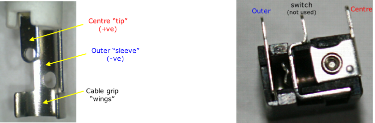
Fig. ME2: 1.3mm plug and 1.3mm socket (Rapid 20-
Making up the cable
It will help if you have a small vice or clamp to hold the plug / socket as you really
need three hands! -
Cut the cable to the length you want. Fit the plug first.
Using co-
Remove sufficient outer insulation.
Remove about 1-
There are different ways of connecting the shield. I tend to favour twisting the strands together tightly, trim off any excess, then solder the end to the outer terminal. This can either be done by putting the twist through the hole (although the twist may be too thick), or just soldering the twist direct onto the terminal. Be careful not to solder where the cable grip wings are, or you may fill the gap up and not have enough room for the wings to bend over properly. Check to make sure there are no loose strands of wire or anything that can short circuit between the terminals. Gently bend over wings with a pair of pliers until the wings grip the cable. Make sure you do not squash the wings too tight and be careful not to cut into the insulation.
The other way of connecting the shield is not to solder it, but to just trim the shield back so that when the wings are bent over to grip the cable the wings trap the shield and that make contact with the shield. Personally, I find this method unreliable because there is always the chance that the shield could break away from the wings and thus lose contact.
Using figure 8 (flat) cable:
Split the cable into two for about 2cm so that you have two individual cables. Remove
about 1-
Whatever method you use, be careful. Don’t be tempted to bend the centre terminal back to give you more access when soldering the wire to it. Whilst there is a bit of give in it, it doesn’t take much movement to snap the terminal off. There is very little space between the two terminals and it is easy to end up with a short circuit, either through a strand of wire or the two joints touching. If the joints seem close together, separate them with a thin piece of insulating material such as a piece of insulating tape or card.
Always check to make sure there is no short circuit between the terminals, it’s very easy for a stray strand of wire to go unnoticed. Although you can check with the plug casing off, a final check should always be made after the casing has been screwed back on as, if space is tight, it’s possible that as you screw the case on, it may push the joints together. Do a visual check before putting the case on and also do a check with a multimeter / continuity tester.
I assume that most people will use the PCB mounting sockets. Remove the case from a plug and insert the plug into the socket. Using a multimeter or continuity tester, identify which is the centre and which is the outer terminal on the socket.
Using co-
Strip the outer insulation as necessary and strip about 2-
Solder the shield to the outer terminal and the inner cable wire to the centre terminal (I usually twist the wire around the terminal and then solder it).
Using figure 8 (flat) cable:
Split the cable into two for about 2cm so that you have two individual cables. Remove
about 2-
Trim off any excess wire. Check to make sure there are no loose strands of wire touching
the other terminal. If you’ve already fitted the plug on the other end of the cable,
then check for continuity and ensure the polarity is correct -
You will need to protect the socket and also try and hold the cable in place as there is no cable grip on the sockets.
The neatest way is to use heatshrink sleeving. use a size that just fits over the socket. I’ve used 1mm.
Cut off a length about 4cm long and push it over the end of the socket and over a bit of the cable. The end of the sleeve should be just on the top of the socket, not hanging over it or it could possibly obstruct the socket hole. Use a hot air source. I used a heat gun on a low setting, but a hair drier should work just as well. If the gun / drier has a nozzle, attach that to help direct the heat. Gently blow the hot air onto the sleeving until it starts to shrink. Move the nozzle around as you are heating to avoid too much heat being concentrated into one place.
The sleeving shrinks to about half its original size, which means that it will be a tight fit over the socket and terminals but, because the cable is much smaller, the sleeving may not shrink to a tight fit over it. As a consequence, the sleeving won’t hold the wire in place, but it does mean that you have a suitable amount of sleeving which you can get hold of when you want to grip the socket to insert or remove a plug. Just don’t pull on the cable. You can wrap a piece of insulating tape over the sleeving / cable join if you want and this will help keep the cable in place.
If you don’t have any heatshrink sleeving, just wrap insulating tape tightly around the socket and first 3cm of cable, making sure that the terminals are fully covered and not sticking through the tape. This might not give such a neat appearance as using the sleeving, but it serves the same purpose.
Test the finished extension cable, making sure that the centre of the plug is connected to the centre of the socket and the outer of the plug is connected to the outer of the socket. Make sure there is no short circuit between centre and outer.
Rapid Electronics also have 1.8m power leads with the plug already fitted (as used to replace faulty PSU leads). If you just want a short extension you could use this lead and just add a socket on the end. The cable has a white identifying stripe on one side, that cable is connected to the centre pin, so connect it to the centre terminal of the socket.
Buying the plugs and sockets
If you just want one plug, Maplin Electronics stock them -
However, you are going to need sockets and Maplin don’t stock them. Both the plugs
and sockets can be bought online and I’ve bought mine from Rapid Electronics, which
are cheaper than Farnell and RS Components. Rapid have their catalogue available
to download in PDF format and I recommend downloading it and looking through it -
The plugs and sockets are on the following pages in their current catalogue:
Plugs
page 94. 20-
page 94. 20-
Moulded lead
page 94. 20-
Sockets
page 94. 20-
page 95. 20-
page 95. 20-
Panel mounting socket
page 95. 20-
No power rating is given for the plugs in the catalogue, so assume that the power rating is 500mA, although it may be 1A (which should be OK)
No power rating is given for the sockets, so assume that the power rating is 500mA (which should be OK)
The panel mounting socket is rated at 5A.
Although the Skeleton socket is suitable, I would recommend the other sockets which are enclosed.
I have some of 20-
Rapid postage is approximately £5. Add 20% VAT to all prices and postage.
Although the total cost is obviously expensive with the postage costs if you only want to order one plug and socket, it works out a lot cheaper per item when you buy more.
E.g. six plugs at Maplin at £1.69 costs £8.54
Six plugs @ 19p, + postage + VAT costs £7.37!
The 1.3mm power connectors are standard on many pieces of electronics equipment. There may be other PSUs that you may like to extend, either now or in the future. For the sake of a couple of pounds, it’s worth buying a stock of the plugs sockets to save having to order them again in the future and pay more postage. I’d recommend a minimum of 10 plugs and sockets, or perhaps 10 plugs, 5 moulded leads and 15 sockets.
You could also order some heatshrink sleeving at the same time -
If you don’t live in the UK, there must be similar online suppliers for your country
www.maplin.co.uk
www.rapidonline.com
Extending the USB cable to 5m
If you want to extend the cable by up to 5m, then you
can just buy a 3m or 5m USB – mini USB cable to replace the one supplied with the
light.
If you want to extend the cable by more than 5m, then there are various options
and these are covered further on.
Extending the USB cable more than 5m
There are ways
of extending the USB cable up to about 20m. Rather than repeat myself here, details,
and hub details can be found on the USB page.
USB Extension trials
You should be able to extend the Madcatz lights using any of
the examples for the Philips lights that are on the USB page.
I have tried out the
following with the two Madcatz lights.
In the following examples, the light was connected
to a single USB port on the PC (unless stated otherwise). Ten Philips systems (wallwasher
and sidelights) were also connected, but through separate hubs / ports on the PC.
The Philips sets had no effect on the results.
1) PC – 5m repeater – 5m repeater –
5m repeater – 2m to one light (total 17m)
2) PC – 5m repeater – 5m repeater – 2m powered
hub – 2m to each light (total 14m)
3) PC – 5m repeater – 5m repeater – 5m repeater
–2m powered hub – 2m to each light (total 19m)
In 2 and 3 I used a powered hub. An
unpowered hub may work for 2, but when the PSU was removed from the hub, the lights
were lost.
The following connections used a pair of Cat5 USB extenders:
4) Connection
using the extenders and 30m network cable to one light (total 30m + 2m)
5) Connection
using the extenders and 30m network cable with the receiver plugged into a hub and
two lights connected to the hub (total 30m +2m (hub) + 2m (light). A powered hub
is necessary
Examples 1 – 5 shown here are just a few of the many possibilities. Results
may vary. I must admit that I was surprised the light still worked with 30m of cat
5, even more surprised that the setup worked with a hub and two lights connected!
I’m certain that when I tried the wallwasher in the past that it wouldn’t work with
30m cable, but then I think I think that, being the control unit, the wallwasher
is much more susceptible to signal loss over long runs of cable.
In all of examples
1 – 5, I tested the lights using Aurora Synesthesia using a sound source. I did not
use it with the display from the screen (I’ll have to try that later).