Speakerlights
The speakerlights are the same as the sidelights, but have speakers added and, on the right light, controls.
The light PCB in the speakerlight is the same as that used in the sidelight. A speakerlight PCB can be swapped with the PCB from a sidelight and vice versa. For operation and details of the light PCB, see the Sidelight pages.
Extending the speakerlight cable -
There is a minor difference to the way the supply is connected to the light PCB (see further down the page for details),
The speakerlights can be divided into three parts:
the light
the speakers and connectors
the controls (fitted in right speaker only)
Speakers and connectors
Two speakers are fitted in each speakerlight and they are both exactly the same.
The speakers are 8 ohm / 10 watts and are connected in parallel. The speaker terminals
are marked + (for red) and -
Unlike the sidelight, where the cable goes direct to the light PCB, the speakerlight cable is split into two (left) or three (right) sections:
-
-
-
The 18v supply for the light PCB connects to the controls PCB first, to supply the 18v for the 5v regulator. A connection is then taken from the controls PCB to the light PCB.
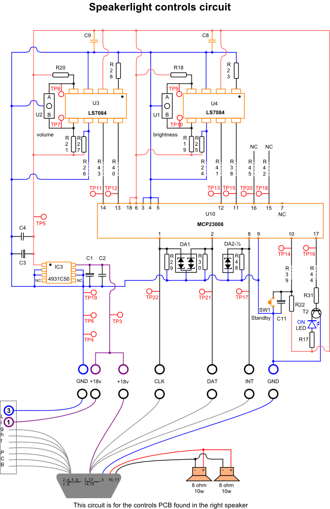
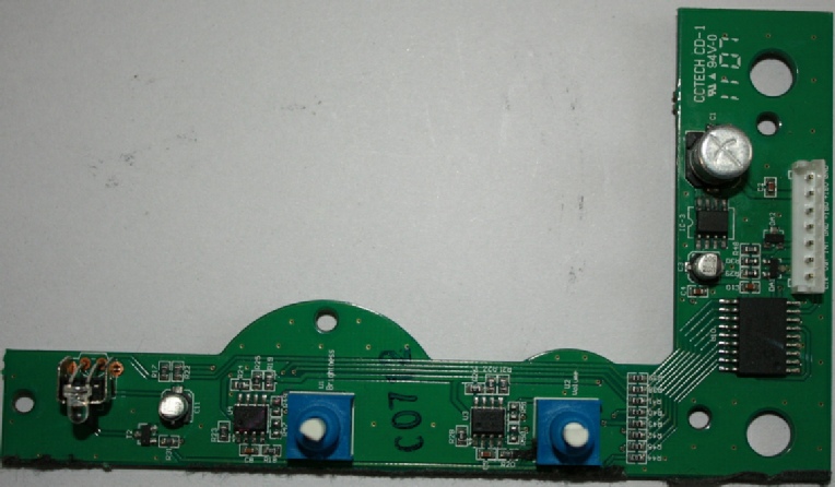
The controls PCB
The right speakerlight contains a volume control, brightness control, standby switch and blue ON LED.
U10 -
U10 is a 8-
Volume / Brightness
The volume and brightness controls are the same, so I’ll just describe the volume.
The usual type of volume control is a potentiometer (pot) that varies the resistance via a wiper making contact with a resistive track. Turn the knob the maximum one way and the resistance is zero or low, turn the knob the other way and the resistance is at maximum. The preset pots on the light PCBs for calibrating the colour are an example of this.
Instead of a pot, a rotary encoder is used. A rotary encoder is basically a digital
control. Instead of varying the resistance, the encoder outputs a series of pulses
as the knob is turned. In encoder U2, there are two sets of pulses -
U2 is connected to U3 -
LS7084 is a quadrature clock converter. It takes the two sets of pulses from U2 and
decodes the information to show the position of the knob and what direction it is
being turned. This is then passed on to the CPU in the wallwasher -
Volume operation
The left and right amplifier output is permanently at maximum. The volume control alters the volume output from the PC itself, in a similar way as if you had turned the volume up / down on the PC. The CPU sends the signal to control the volume via the USB bus.
Standby
Switch SW1 is a momentary push-
If the wallwasher is on, pressing SW1 will put the wallwasher to standby. If the wallwasher is in standby, pressing SW1 will turn the wallwasher on. Holding SW1 in will not make any difference.
ON LED
The blue LED shows when the wallwasher is ON. Unlike the red LED, which is not connected to the CPU, the blue LED is controlled from the CPU via U10.
5v supply
Voltage regulator IC3 provides the 5v supply for U3, U4 and U10. The input voltage comes from the 18v supply that also goes to the lights PCB. This 18v supply is always on as long as the speakerlight is plugged in and detected.
Various test points are located on the underside of the PCB. The metal fixing for SW1 is connected to GND and makes a useful ground point when doing voltage measurements.