Amplifier
It is unlikely that there will be a circuit diagram or specifications for the amplifier PCB
Description
The amplifier PCB has a power input of 15-
The audio signal is fed to the PCB via the audio in socket and is then split to two
amplifier chips -
There is a bass control which controls the volume level on the subwoofer speaker. This is the only control directly associated with the amplifier.
PCB connections
There are five plugs / sockets on the PCB and one soldered connection:
3-
7-
3-
3-
3-
Soldered wires to subwoofer speaker
All the plugs are accessible without having to remove the PCB. The AC supply plug is most easily accessed from the front or top of the box.
There are three main chips on the heatsink:
IC101 -
IC302 -
BD400 -
The heatsink gets fairly hot -
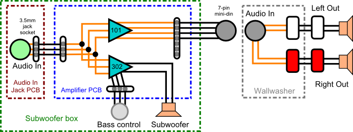
Fig. BA1: Subwoofer audio block diagram
Removing the amplifier PCB
You will need to remove the front of the box
Disconnect the subwoofer from the mains supply
Remove the 7-
Remove all plugs from the PCB
The bass control cable from the front of the box plugs into the PCB and is also held in place by two twist ties which are soldered to the PCB and are wrapped in foam.
Remove the foam and untwist the ties.
The AC In plug / socket on the PCB can be accessed through the round hole at the front of the box. The plug is the same type as used for the mains connections on the relay PCB and has a tab which must be pushed in and held in as you gently remove the plug (see the Subwoofer Relay PCB page for the tab information).
The PCB is held in place by 6 screws
The screws can be accessed from the square hole in the rear of the case and the round hole from the front of the case by using a “stubby” (short) screwdriver. A Philips size 2 should be OK..
You will probably find it hard to replace all of them, though as it will be difficult to get some of the screws back in the holes unless you can also access the PCB through the top of the box (use a longer screwdriver).
There is a rectangular block of wood glued inside the box, above the black heatsink.
This keeps the heatsink / PCB in place and needs to be removed -
The PCB needs to be rotated 90 degrees, so that the heatsink is above the PSU before the PCB can be removed from the case or put back.
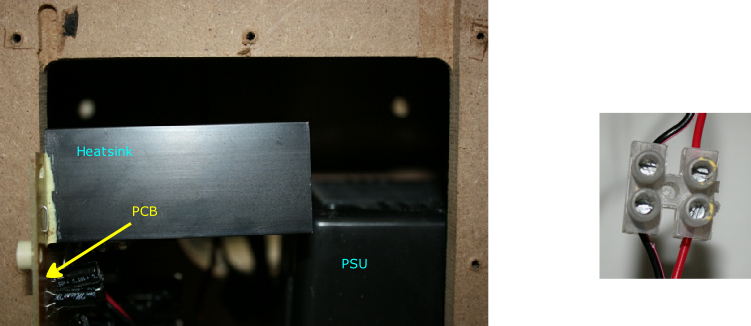
Fig. BA2: Removing the amplifier PCB -
The red and black wires from the subwoofer speaker are soldered directly onto the
PCB and will restrict how far the PCB can be removed from the case. If you want to
remove the PCB completely, then you could cut the wires at a suitable point -
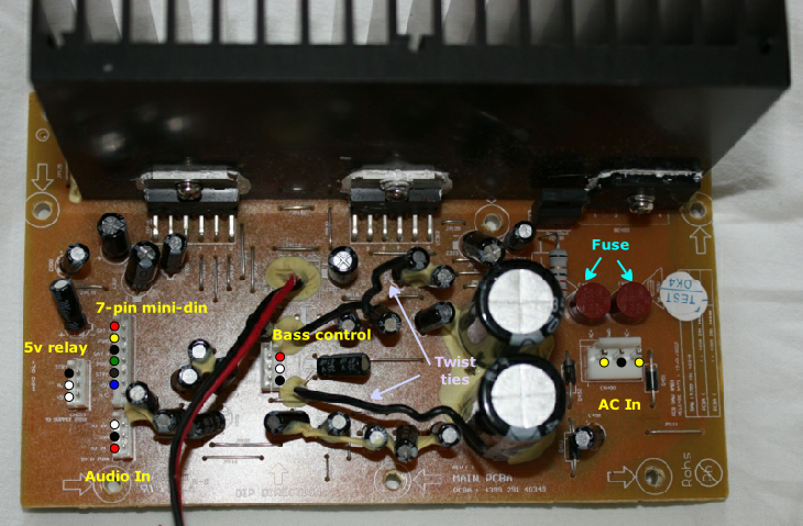
Fig. BA4: Amplifier PCB and socket identification

Fig. BA5: Amplifier PCB track side -
Testing the amplifier
The amplifier PCB also includes power supply regulation components. Details of these and testing the power supply are on the Subwoofer and speakers / Subwoofer PSU page.
If you are testing the amplifier with the PCB out of the box, make sure that the PCB is not resting on anything metal that can cause a short circuit on the PCB track side.
Before you carry out any tests on the amplifier, check the PCB for any obvious signs of problems, such as a “cooked” / overheating component, loose component etc.
Check the track side of the PCB with a magnifying glass, looking for any signs of dry or loose solder joints, or for any hairline cracks on the tracks or solder.
Flex the PCB VERY GENTLY! a tiny bit to see if there are any obvious signs of cracks.
See cracked PCB and joint problems at Faults and Repairs / Repairs / Repairing a PCB
The amplifier can be tested without the bass control cable connected, but the subwoofer speaker will not work as the input for the subwoofer speaker amplifier IC302 goes through the bass control pot. The white wire (OUT) is the input to the amplifier from the pot.
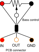
Fig. BA6: Bass control pot connections
To test the amplifier, you will need to have:
The 7-
The subwoofer mains cable connected to the wall socket and switched on
The speakerlights connected to the wallwasher
The audio cable connected between the PC and the subwoofer
An audio output from the PC
Testing the amplifier when on
It’s possible that you may be able to test the amplifier PCB, with the PCB in place, through the top of the box with the speaker removed. This is the simplest way because it means that everything except the speaker can remain connected as normal. However, access is restricted and you may find it easier to test it with the PCB out of the box.
Because the 15-
Warning
The track side of the relay PCB will be accessible and will have mains voltage present!
Connect the subwoofer mains plug to the wall socket via a RCD (see the Faults and repairs \ Repairs page for more information). Cover the relay PCB the best you can to prevent any accidental touching.
The bass control pot will have to be disconnected because of the short cable. If you want to test the subwoofer speaker or the subwoofer part of the amplifier, you will need to make temporary connections between the pot and the ends of the (unsoldered) wires, or just twist the red and white wires together. This will give you full subwoofer speaker volume.
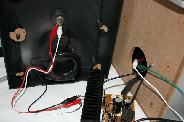
Fig. BA7: Live testing the amplifier
This photo shows one way of connecting the amplifier PCB out of the box (the relay PCB and connections are out of sight on the right). The white and green cables go to the subwoofer speaker