Calibrating the lights
When the lights are made, they are calibrated at the factory to ensure they show the correct light level and hue. This means that if two sidelights are next to each other, they should both look exactly the same. However, sometimes there is a slight variation in the colour on one of them, perhaps a white light looks slightly bluer. It’s possible for you to do your own calibration of the light to try and match the colours exactly. Whilst making the adjustment is easy, getting the colour exactly right may be very time consuming and take a lot of patience. Personally, I wouldn’t bother with calibration unless it’s really necessary.
First, the basics
The red circuit will be used as an example.
Each colour circuit has a preset potentiometer (pot). A pot is a resistor that has the resistance spread out along a track. The pot has a wiper with a contact that can be moved across the track. The amount of resistance at the wiper will depend on its position on the track. By adjusting the wiper, the amount of resistance (and the LED brightness) can be varied in order to calibrate the lights.
The pot is represented by the symbol below. Pin 1 is one end of the resistor, pin 2 is the other end, and pin 3 is the wiper. The wiper is represented by the arrow. There is a hole in the top of the wiper, and a screwdriver can be inserted in the hole and turned to turn the wiper. If you look at one of the pots on the PCB, you will see there is a small indent or bulge at the top of the wiper blade, above the screw hole. This is the part of the wiper that touches the resistor track below. The pot has a nominal resistance of 100 ohms (100R), although there is a high percentage tolerance of possibly up to 30%, so the actual value can vary greatly.
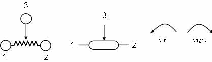
Fig. C1a: Preset potentiometer (pot) diagram symbols and adjustment direction

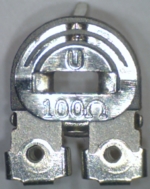
Fig. C1b:
Left
A pot similar to that used on the PCB (this one is bigger)
The indent at the top of the wiper can be clearly seen
Right
The wiper has been removed and the resistor track can be seen
When adjusting the pot, it is important to use the correct screwdriver -
Warning
Do not turn the pot to the maximum brightness -
In the red circuit, R49 is the pot. Pin 1 is not connected, pin 2 is connected to GND and pin 3 is the wiper which is connected to the transistor T1 and to input pin 2 of IC1. Varying the resistance of the pot changes the voltage going to IC1. This change affects the output from IC1 (at pin 1) which goes to both group 1 and group 2 LEDs’ transistors. As a consequence, turning the pot wiper in either direction will vary the brightness of all the red LEDs. Turning the wiper to the left will dim the LEDs, turning the wiper to the right will brighten the LEDs. The position of the wiper may vary depending on the LED colour. When adjusting a pot, never turn it fully left or the brightness will be too high. There should never be a reason for the pot of any colour to have to be adjusted fully to the left or right.
The purpose of the pots in the lights is to be able to correct any variations in the actual values of the components used in the different lights and thus be able ensure that if you have two lights side by side (or the three in a wallwasher) they will look the same colour.
White light is made up of the three colours all set at the same level in the DirectControl panel, normally at maximum. Adjusting one colour by varying the brightness makes that colour more or less dominant. For example, if you switch the red off, you will be left with blue and green, which makes cyan. This can be shown by playing around with the spectrum of one of the lights in DirectControl panel. See how the brightness of the different colours vary between full on and off to produce the 16+ million colours that are available from the light.
Whilst a pot only adjusts one colour, you will find that the pots for the three colours interact. If you find that the white light looks a little bit too blue, you may decide to turn the blue brightness down. You may now find that the light has a slight pink tinge, and so you turn the red down, and so on. If you’ve ever tried to adjust the colour on a monitor to get it looking just right, you’ll know how difficult it can be sometimes.
Adjusting the colours
On the sidelight, R49 is the pot to adjust the red brightness, R47 is the pot to adjust for the green brightness, R44 is the pot to adjust for the blue brightness.
On the wallwasher LED panels, R49 is the red pot, R50 is the green pot and R51 is the blue pot. The actual colour is marked on these PCBs
Before adjusting, mark the position of the centre of the wiper on the PCB, preferably with a fine tip permanent marker so it doesn’t get erased. Or, if you have a multimeter, make a note of the resistance reading (with the light unplugged) between pins 2 and 3 so at least you can always return to those settings and start again if you mess up.
You shouldn’t need to make a big adjustment, only adjust the pot wiper in tiny steps, checking the light after each step. If you find that the colour goes off after you’ve made an adjustment, adjust the wiper a bit to the left or right. Sometimes the contact between the wiper blade and the resistor film can be poor..
You will probably find it very difficult to adjust the pots to get the colour exactly as you want it and it may take a lot of patience to get it right. Adjustment of the sidelight colour is made more difficult by the fact that you can’t see the LEDs as you’re making the adjustment. Also, when comparing the light from two adjacent sidelights, you will need to have the opaque shades in place on both lights because the light looks different with the shade on or off.
If you have a multimeter, you could compare the resistance readings of the same colour pot on other similar lights, although having the same resistance doesn’t necessarily mean that the the light will be exactly the same, and there can be a wide difference in the reading for the same colour. This is partly due to the tolerance of the pot resistance. After all, the purpose of the pot is to be able to adjust the colour brightness so that the lights will look the same when next to each other and on the same setting such as max white.
As an example of the difference, the readings below are taken from the pots on two
sidelights. You can see that there is a big difference in the resistance of blue
pots. The resistance in brackets is the resistance of each pot between pins 1 and
2 -
Light 1 Red 44R5 (96R3) Green 69R8 (103R6) Blue 54R8 (101R5)
Light 2 Red 45R8 (92R7) Green 65R0 (93R1) Blue 73R0 (91R3)
Measure the resistance between pin 2 and pin 3 on the pot (the reading for pin 3 can be taken anywhere on the wiper surface).
Flickering LEDs or no LEDs lit
If you find that you have all of one colour LEDs flickering, or no LEDs of one colour lit, either when you’ve adjusted the pot or at some time afterwards, it’s possible that there is a poor contact between the wiper and the pot of that colour. Move the wiper of the pot slightly to the left or right to see if that clears the fault.
Also see Flickering LEDs on the Sidelight\Sidelight faults page