Sidelight / Speakerlight light faults
The information and descriptions given here are based on a sidelight PCB. “All of
one colour” or “whole group” means what it says -
When describing the possible causes for a fault, I am assuming that the PCB itself
is not faulty -
The test points are a useful means of checking whether everything is as it should be and help to pinpoint where something might be wrong.
The sidelight PCB gets quite warm -
Potentiometers can be another source of problems (see calibrating for potentiometer details). The pot track can get worn or dirty. The pots used are a standard type, but they are “cheap and nasty” and I’m certain they’re not really suitable. The current passing through R49 from group 1 red LEDs is 0.014mA (0.25w) and the current passing through R44 from group 1 blue LEDs is 0.016mA (0.3w). This is a lot of current and I suspect that the track on the pot eventually gets damaged / burnt out at the point where the wiper makes contact. This can give an intermittent contact (flickering light) or an open circuit (no light). If a pot needs to be replaced, replace it with one of a better quality, higher wattage type.
Unless stated otherwise, all measurements are between the measuring point and GND (i.e., with respect to earth). GND being TE8 or J5 pins 3, 5 or 7
Refer to and follow the circuit diagram.
At present, I’ve only had a faulty LED, so some of the information is guesswork. However, I think it is correct.
Working on the PCB
When working on the PCB, remember that it is “live” if it sidelight is plugged into the wallwasher and the wallwasher is switched on. Even if the light has been switched off in the DirectControl panel etc. The VCC supply is still present. Because of the closeness of the components it is very easy to short circuit something and potentially damage one or more of the components. Ensure there is nothing metal on the work surface you are using that can potentially touch any of the components. Always keep screws, probes etc. Away from where the PCB might be resting. Remember, there are contacts on either side of the PCB.
Always unplug the light from the wallwasher before removing or inserting the plug that goes into connector J5. Be careful when moving the PCB. If the attached cables are flexed too much, eventually they could break. When removing or inserting the plug, take care not to damage or bend any of the pins. The plug can be quite stiff. Never try and remove it by tugging on the wires. Use a small flat blade screwdriver between the base of the plug and the connector and gently lever it up a bit. Go to the other end and do the same. Repeat this process until the plug is fully removed.
Where is the fault?
There are various reasons why a sidelight doesn’t work, including:
faulty component
faulty connection
faulty wallwasher
It’s necessary to try and identify the cause, usually by a process of elimination
First of all, go to the DirectControl panel and make sure the light(s) are switched on, enabled and the height is set to None. Make sure the lights are set for white light and are set at maximum brightness. White light means that all three colours, Red, Green and Blue, should be lit.
Check the plugs
If the sidelight plug is not fully in place, it’s possible that some contacts could still be made. Depending on what are making, you could have no colours, one colour or two colours lit. A loose plug could also cause an intermittent light operation.
Check that the light is fully plugged into the wallwasher and tighten the plug’s thumbscrews to hold the plug in place.
No lights working at all
Suspect the wallwasher
Important
See Faults and repairs for precautions you should take before taking the light apart.
One light not working (no lights at all)
Note
The 18v VCC must be present on pin 1 of the wallwasher socket (and thus on pin 1 of the sidelight PCB connector J5 and PCB test point TE9) or the light will not work.
The 18v is only available when pins 9 and 12 are shorted together (see the sidelight
pin-
Prove whether it is the light or the wallwasher that is defective by trying another sidelight in the same socket. A red plug can go into a white socket and vice versa. (I assume that sidelights with speakers can still be connected this way, although you may lose the speaker / light controls).
If the light lights up in a different socket, then suspect the wallwasher. If the same light still doesn’t light up, then that light may be faulty.
A light not working could be caused by:
faulty plug
defective cable
poor contact on jumper J5 on the light PCB
a fault on the PCB (PCB or component fault)
Check that the plug and cable aren’t damaged. Try moving the plug slightly in the
wallwasher socket -
With the light plugged in, try flexing the cable up and down -
Dismantle the sidelight so that you can access the PCB. Ensure that Jumper J5 is fully secure and pushed in straight. J5 is normally a tight fit. Unless you’ve taken the light apart before, it’s unlikely that J5 is the problem.
Using a multimeter, do the following measurements, either between the test point (TE) or J5 pin (J5/X). Pin 1 of J5 (normally the black wire) is on the left (next to J6). VCC should be approximately 18v, the colour inputs should be approximately 16v
TE9 to TE8 (J5/1 to J5/7) = VCC to GND
TE7 to TE8 (J5/2 to J5/7) = Red in to GND
TE6 to TE8 (J5/4 to J5/7) = Green in to GND
TE4 to TE7 (J5/6 to J5/7) = Blue in to GND
If the voltages are not correct
If the voltage is 0v, then there is probably a break in that wire or a poor connection at the plug. If VCC is less than what it should be, this would affect all colours. As long as VCC is correct, a break or poor connection on one of the colour wires will only mean that that colour is lost.
It is very unlikely that a poor connection or a faulty cable would affect all the wires.
Unplug the light. Disconnect J5. Plug the light back in. Do the same tests again, this time testing between the holes on the J5 connector. Use a thin piece of insulated wire to go between the hole and the multimeter probe.
Test between the holes connected to the following wires:
Black to Blue = VCC to GND
Brown to Blue = Red in to GND
Orange to Blue = Green in to GND
Green to Red = Blue in to GND Note, the Red, Yellow and Blue wires are all GND. Using the green instead of blue wire socket means that the two wires you are putting in the holes will be further apart, thus there will be less chance of them accidentally shorting against it other during the test.
If this test shows the correct voltages, unplug the light, connect J5 back again and plug the light back in. Repeat the tests between the test points / J5 pins. If the voltages are now showing incorrectly again, it’s possible that there might be a short circuit on the PCB or one of its components, such as a capacitor.
If the voltages are correct
If all the voltages are correct when J5 is connected to the PCB, then the connection between the wallwasher and light PCB should be OK and the fault is somewhere on the PCB.
Although the colour circuits are separate on the PCB, they all share VCC GND and
IC1. IC1 has four op-
Refer to the normal readings diagram on the Circuit page.
VCC has been tested and proved OK, so that leaves IC1. Check the three colour outputs of IC1. The places to check are:
Pin 1 (at the junction of R7 and R8 -
Pin 7 (at the junction of R13 and R29) -
Pin 8 (at the junction of R19 and R39) -
If the voltage is wrong, check the voltage at the input pin:
Pin 2 (wiper of R49)
Pin 3 (junction of R4, R5, C1)
Pin 5 (junction of R10, R11, C2)
Pin 6 (wiper of R47)
Pin 9 (wiper of R44)
Pin 10 (junction of R16, R17, C3)
If the voltage at the input pins is correct, IC1 is possibly faulty
The voltage at both input pins on IC1 is normally the same for the IC output voltage to be normal.
It is difficult to test the voltage on the pins of IC1 without the risk of shorting an adjacent pin. The photo below shows other components that the pin is connected to where you can use them to take a reading from instead of the pin. All the same colour dots go to that pin. Make sure you use the correct end of the resistor, as shown by the position of the dot.
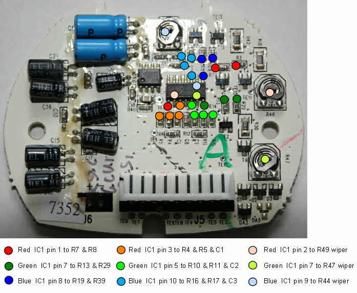
Fig. SF1: Places that can be used to test the voltage at IC1 pins
Replacing the plug / cable
See extending the sidelight cable for further information
One light partly working
Normally this would be all of one colour not working, or half of one colour not working
-
All of one colour not working
The red circuit will be used as an example. Refer to the circuit diagram for the equivalent components in the other colour circuits.
No red LEDs
Swap the lights over and try them in different sockets -
Confirm their is a red input voltage at TE7 on the light PCB. The reading should be about 16v at maximum brightness.
No voltage?
Disconnect J5 and measure the voltage between holes 2 and 3 (normally the brown and
red wires). If there is no voltage, the fault could be in the cable or the plug
connection. Check them out and replace as necessary -
If there is a voltage on the PCB when you checked TE7, the fault is somewhere on the PCB.
Try adjusting pot R49 slightly to the left or right. (See the Calibrating page for
details of how the pot works). If the red LEDs now light, R49 may be faulty -
Warning
Do not turn the pot to the maximum brightness -
If there is still no red after adjusting R49, it’s possible that R49 may be open
circuit. R49 can be temporarily by-
You can also test to see if R49 is open circuit by measuring the resistance between pin 1 and pin 2. This should be around 100R. If the resistance is higher than 200R, then R49 is faulty.
If the red LEDs are still not lit after testing R49, then
Test the voltage between the wiper of R49 and GND
Test the voltage at the junction of R4/R5/C1 -
the two voltages should be the same
If the reading at pin 2 and pin 3 are the same, then test voltage at the junction
of R7/R8 -
If the reading at IC1 (pin 1) is wrong, an the readings at pins 2 and 3 are correct,
it’s possible that the op-
The diagram below shows a real example of the readings when the pot -
The symptoms are all of one colour not working.

Fig. SF2: R49 open circuit
R49 is open circuit, or the wiper of R49 is not making contact. The input at pin 3 of IC1 is normal. Because there is no path to GND, the voltage at pin 2 of IC1 is higher than normal, and higher than that at pin 3. As a consequence, there is no output from IC1 and so T1 and T4 are switched off. Both groups of LEDs are off. The voltage at the LEDs will be the same as when the light is switched off.
R49 can be tested for an open circuit by measuring the resistance between pins 1 and 2. The pots have a wide tolerance, and the resistance may vary a bit from the nominal 100R. Of six tried, the resistance varied between 91R3 and 103R6.
One other test could be by temporarily connecting an ordinary 47R or 56R resistor between terminal 2 and the wiper of R49. If all the LEDs now light, then R49 is probably faulty.
If R14 was open circuit instead of R49, this would not affect the output of IC1 as
R14 does not go to IC1. With the light switched on, the voltage readings would be
the same as normal, except that the voltage across group 2 LEDs and TE11 will be
about the same as those when the light is off. Only group 2 LEDs would be affected.
Although T4 is switched on, there is no return path to GND for LEDs 15 -
R14 can be tested for an open circuit by measuring the resistance across it -
Another test can be done by piggy-
Although a fairly large current passes through R14, it is less likely to fail than a pot. Eliminate all
other reasons for loss of one group of LEDs before replacing the resistor.
Only one group of LEDs working
This means that one group of LEDs is working, the other group isn’t. The red circuit
will be used as an example. We’ll assume that group 1 (LD4 -
The fact that one group is working proves that there is a red input and IC1 is working correctly. The fault lies with a component within that group. These are: R8, T4, R14, LD15, LD14, LD13, LD16 (in that order). If any of these fail, that group will not light.
The LEDs are connected in series, like fairy lights, so if any one of these becomes open circuit, the path with be broken and none of the LEDs will light.

Fig. SF3a: All LEDS working Fig. SF3b: One LED
faulty -
Current flows between VCC and GND, with the transistor acting like a switch. This switch is turned on / off via IC1.

Fig. SF4a: No input -
You need to be able to identify where the fault is. Set up the light so that it is at maximum white. Check the reading at test point TE11. If it is showing 0v, then there is no VCC coming through the LEDs. This means that one or more LEDs are faulty, causing an open circuit. If there is a voltage at TE11, such as the voltage when the light is switched off, it may mean that the transistor hasn’t switched the LEDs on. Check the voltage at the junction of the output from IC1 (pin 1) and R7 and R8. If the voltage is correct, (which it should be if the other group of LEDs are lit), either resistor R8 is faulty (check for a voltage at the junction of R8 and T4) or the transistor is faulty. Test the LEDs as detailed on the Testing LEDs page, just to make sure s faulty LED isn’t giving a false reading. If the resistor test between TE11 and ground lights all the LEDs, then that proves the LEDs are OK
If the reading at TE11 is 0v, then you will need to test the LEDs to identify which one(s) are faulty.
If the junction with T4 and R14 is showing a voltage then R14 might be defective.
The diagram below shows a real example of the readings when one of the LEDs in a group (LD16) is faulty.
The symptoms are no group 2 red LEDs lit.

Fig. SF5: voltage readings with LD16 faulty
Only one LED not working
If one LED in a group is not lit but the others are, it’s possible that the LED has an internal short circuit and, although it’s not lit, is providing a path for VCC to reach the next LED or transistor. Replace that LED.
Another reason for one LED in a group not lit is if there is a short circuit across its terminals. This is very unlikely, but check the PCB around the LED just in case.
Flickering LEDs -
If all one colour (both groups of that colour) LEDs flicker, then this could be for the same reason as for all of one colour not working, except that the fault is intermittent. Some people have reported that this only occurs when the lights are full on, but the light works normally if the light is dimmed. From reports, this defect mainly seems to occur on the lights in the wallwasher, but it has been reported on sidelights.
Although LEDs use a lot less current than normal filament bulbs, they do generate some heat. In a wallwasher, there is also the additional heat from other lights and components on the main control board. It’s possible that their may be a dry solder joint on the within that colour circuit on the PCB and the heat is causing the joint to expand slightly and cause a poor contact. However, as with no LEDs, my first suspect would be the pot. When the LEDs are on maximum, they are drawing the maximum current. This passes through the wiper connection and resistor surface on the pot. It’s possible that there is a poor connection between the pot wiper and the resistor surface, or the pot is faulty.
Warning
Do not turn the pot to the maximum brightness -
Note -
See the information under All of one colour not working for the tests that you can do.
Flickering LEDs -
If all one colour (both groups of that colour) LEDs flicker, then this could be the
same reason as for all of only one group of LEDs not working, except that the fault
is intermittent. The same comments made in flickering LEDs -
This could also be due to a faulty LED in that group -
If a LED is faulty, you could try the substitute LED test, although this might not
work if the fault is caused by a dry joint. If you suspect that a dry joint is the
problem and you know where it is, just resolder that joint. Beware of excess heat
that could damage components, especially the LEDs -
See the information under Only one group of LEDs working for the tests that you can do.